


The 'Search' and the 'Fix'
THE SEARCH:
Although my logic told me it could not be due to the physical length of the coax, I wanted to check this first.
I disconnected the 14m AB-5 running to the antenna and connected it to a 75 ft. length of LMR-240 coax (approximately the same length as the next section of AB-10 coax).
I spread the LMR-240 out on the ground, running it around in a big loop, directly underneath the short leg of the 807-HDL.
I measured the SWR with a 2 MHz scan and the junction of the two pieces of coax un-grounded. NO DOUBLE-DIP.
I grounded the junction of the two pieces of coax and measured again.
STILL NO DOUBLE-DIP.
I moved the position of the LMR-240 a few times and re-measured.
STILL NO DOUBLE-DIP.
I concluded that the problem was not due to the length of the coax, so it had to be the position/location of the Airborne-10 coax that was causing the trouble.
THE LOGICAL THING TO DO would be to just move the AB-10 coax.
Unfortunately, there was no way to do this.
The coax runs through a jungle-like area in our yard, which I cannot navigate:
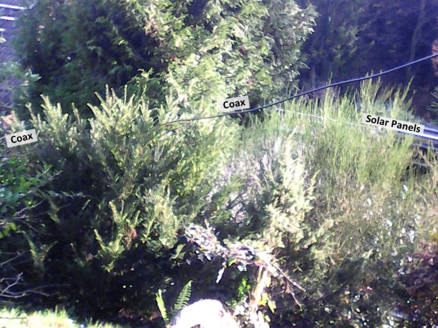
As you see, there is no way to work in that jungle!
But do you see what's in the back on the right?
"Solar Panels"
This gave me an idea. What if the signal on 20m is reflecting off the (metal) backs of the solar panels and striking the AB-10 coax? That would cause Common Mode Current to be induced into the coax.
I had no way to prove or disprove this theory, but I had an idea about how to perhaps stop it.
THE FIX:
As I said earlier, I have seen this double-dip before, during my extensive Common Mode Current test in 2013:

In this test, I created a "Worst Case" Scenario for Common Mode Current (CMC), then measured the antenna, first with a single-core and then with a dual-core 4:1 Guanella balun in the antenna.
- The Dual-Core balun was struggling with blocking the CMC; its SWR curve was distorted by the 105 mA of CMC on the feedline (with 100 W. of RF applied).
- The Single-Core balun failed misserably, exhibiting a double-dip in SWR; one below the band and one above the band.
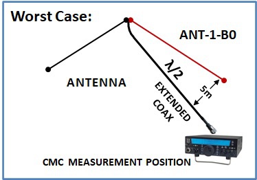
Worst Case Configuration
To creat the worst case, I extended the coax to a full physical half wavelength (x 0.98). According to G3TXQ (SK), this is the length prone to have the most CMC.
Then I skewed the coax to the side as shown in the drawing on the right.
With a good 4:1 Guanella balun I got the distorted SWR curve shown in the photo above on the right. The bad 4:1 balun (i.e., single-core) returned a double-dip in SWR as seen in the picture above, on the left.
NOW BACK TO OUR 807-HDL SWR ABNORMALITY PROBLEM:
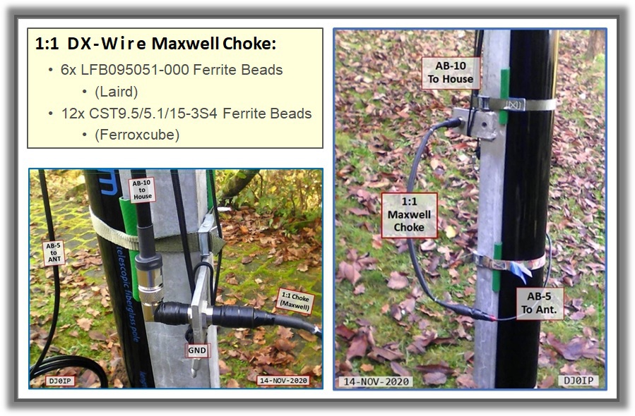
I suspected the double-dip was caused by CMC on the feedline and the only means I know of to get rid of it, other than moving the coax (which was not an option), is to add a choke.
I inserted a good 1:1 Maxwell Choke between the AB-5 coax running up the pole, and the AB-10 coax running towards the house, with the AB-10 side grounded.
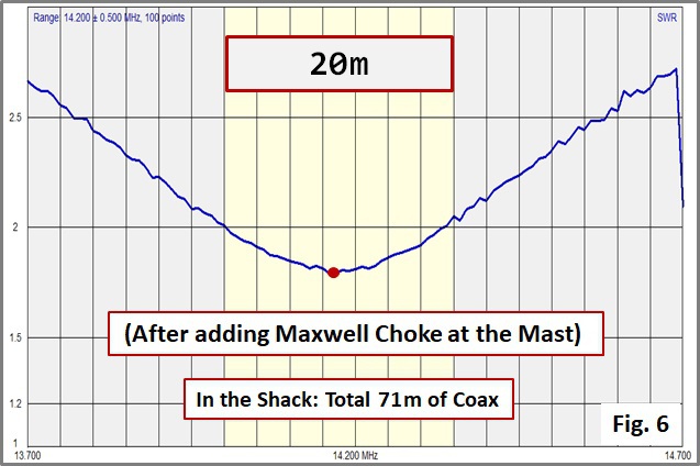
My efforts were rewarded with the following SWR Curve on 20m in the Shack:
And now a look at the "BEFORE" and "AFTER" Curves:

The 20m SWR Curve now looks as it should:
- The Double-Dip is GONE!
- The Level of SWR is much lower
- The Curve is Centered in the Band
- No need for an Antenna Matchbox
CONCLUSION:
Common Mode Current (CMC) is a Terrible Monster that feeds on Coax. It can do all sorts of nasty things to our station as well as to our neighborhood.
Most of us are aware of a few of the things it does, i.e.:
- RF in the Shack
- Electro-Magnetic-Interference (EMI) to Consumer Devices in our house or the neighbor's house
However, many are not aware of the other negative effects of having CMC on the feedline. Here is a list of what I discovered during my 2013 Field Test of Common Mode Current:
- Bogus SWR Reading; it may read higher or lower than the actual value.
- SWR Reading Sensitive to the touch; touching a metal antenna analyzer results in swings in the level of SWR.
- SWR changes when Grounding the Analyzer
- Skewing of SWRmin; The frequency at which minimum SWR occurs is skewed, usually up the band.
- Skewing of the ‘Shape’ of the SWR Curve across
the band.
- Estreme cases may even result in a DOUBLE-DIP in SWR.
- The SWR Reading is Coax-Length Dependent; Even short changes (i.e. 10 ft.) in the length of the coax will cause a measurable change ins SWR.
If you are experiencing any of the above, you most likely have Common Mode Current on your feedline and should address the problem.
DOUBLE-DIP IN SWR = CMC on the COAX