


SWR Curves
READ ME FIRST:
When we speak of lengths of coax in terms of wavelengths, half-wavelengths, etc., we must specify whether we mean "physical" or "electrical" wavelength. There is a significant difference. I will refer to them as eWavelength and pWavelength for clarity.
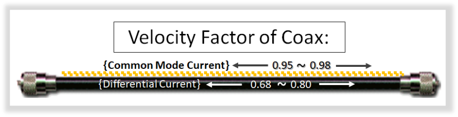
Also, when we speak of the velocity factor (vf) of a coax, we are usually speaking of its vf "inside" of the coax, where Differential Current is flowing. For instance, most normal coax has a vf of 0.66, whereas most foam coax is about 0.80.
BUT, when referring to Common Mode Current flowing on the "outside" of the coax, we must use the vf determined by "the outer surface of the shield and the jacket of the coax." This is usually between 0.95 and 0.98 for all types of coax, so in general I often just quote the physical length.
The photo/drawing below depicts this:
The SWR of My 807-HDL Special:
In order to understand exactly what is happening along the long coax run between the antenna and the house, I made several sets of SWR measurements along the way.
Stake in the Ground: 1/2 eWavelength of RG-58 AU (cut for 3.480 MHz).
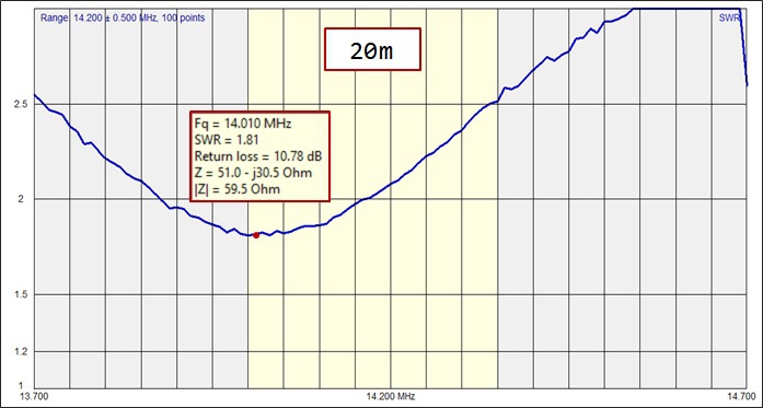
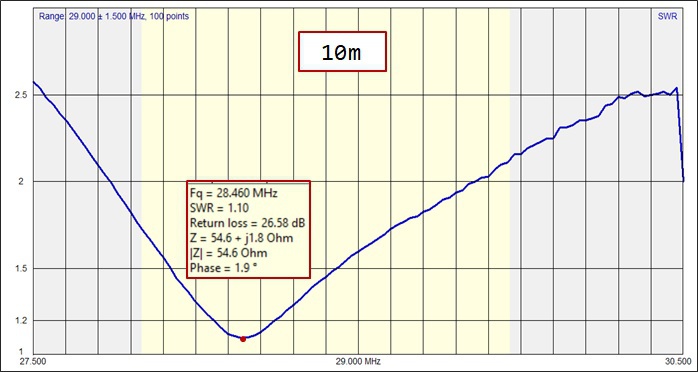
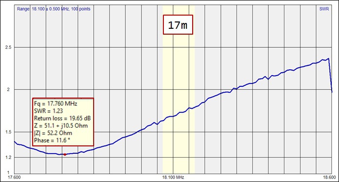
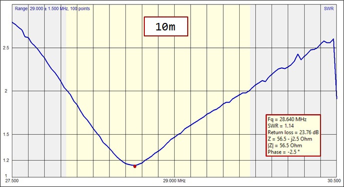
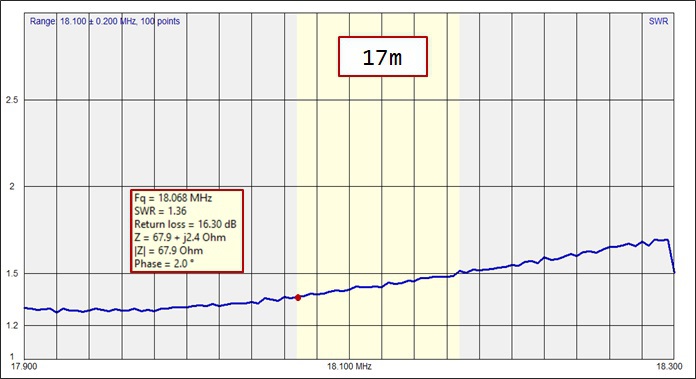
- This length reproduces values close to the feedpoint impedance on the classic hf bands (80/40/20/10m) as well as on 17m.
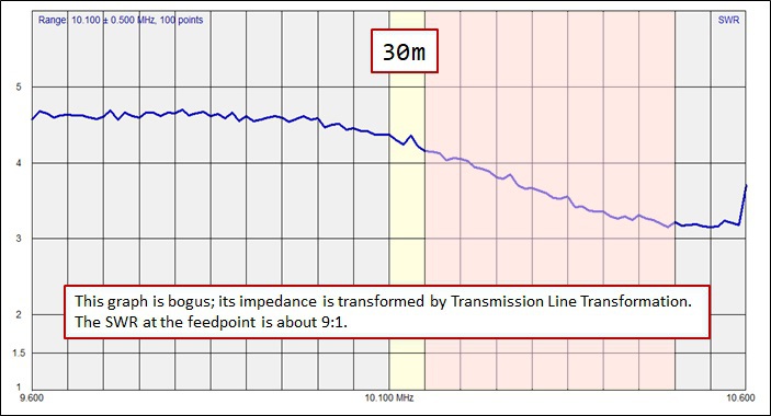
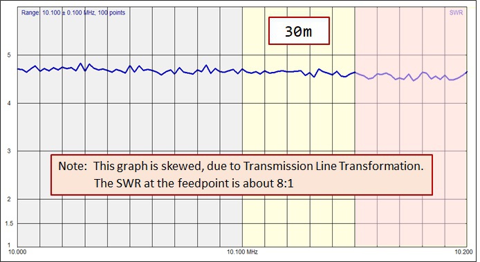
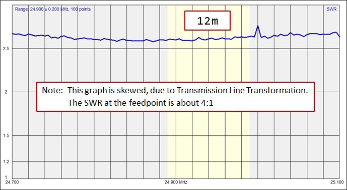
- The impedance on 30m is significantly skewed, and on 12m somewhat skewed (both showing lower SWR values than at the feedpoint).
The coax run is broken up into 4 segments:
- 14m of Messi & Paolomi Airborne-5 (running up the
pole)
- Measurements #2
- 24m of Messi & Paolomi Airborne-10 (running from the pole to
the terrace)*
- Measurements #3
- 30m of Airborne-10 (running from the terrace to the
house/shack
- No Measurements take at this point.
- 2m of RG8U running through the wall, into the house, and to the
station
- Measurements #4
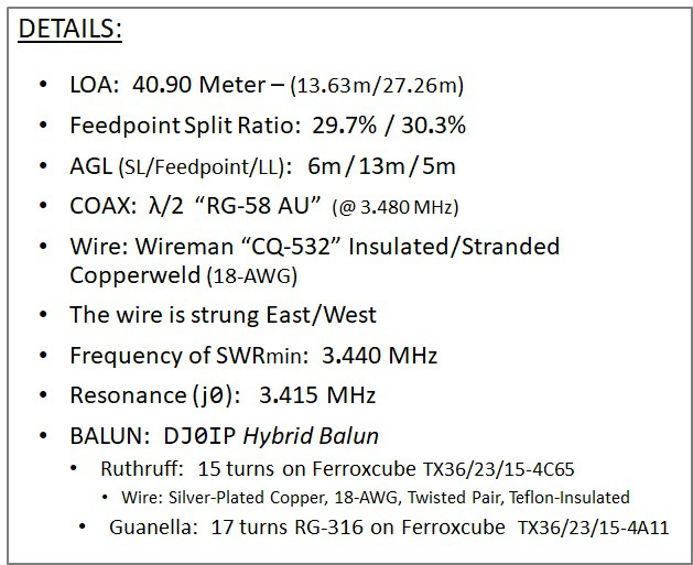
*This is a total of 38m of coax (14 + 24), which together with the 1m of coax in the 1:1 Guanella Choke before the final 30m attaches, approximates a physical 1/2 wavelength of coax; this is the theoretical point where Common Mode Current should be at it highest level.
A 1:1 Maxwell Choke is inserted between the RG8U and the Station.

Airborne-5 is a very lightweight 5mm dia. coax with much less loss than RG-58. This is only used to run up the telescoping fiberglass pole.
Airborne-10 is a lightweight, high-performance 10mm dia. coax. It runs from the pole, all the way to the house.
RG8U is a 5mm coax used only to run through a hole in the wall of the house, to the operating table.
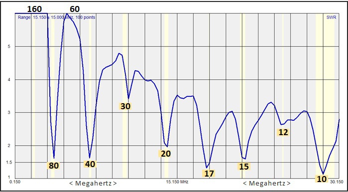
BEGIN: 1/2 eWavelength (w.l.) of RG-58 AU Coax attached to the antenna - cut for 3.480 MHz.
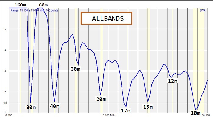
From past measurements on this OCFD design using several different lengths of coax, including multiples of 1/2 e-w.l. on each of the WARC bands, I have determined that measurements with this half e-w.l. of coax on 80m yields realistic results, very close to feedpoint impedance, on all "classic" HF bands (80-10m), plus 17m. The SWR on 30m and 12m is usually skewed, unless the coax is close to a multiple of an electrical half wavelength on that band.
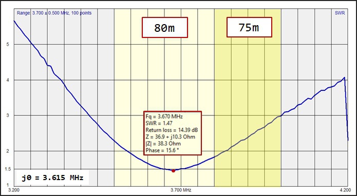
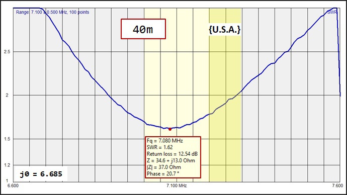
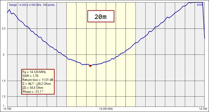
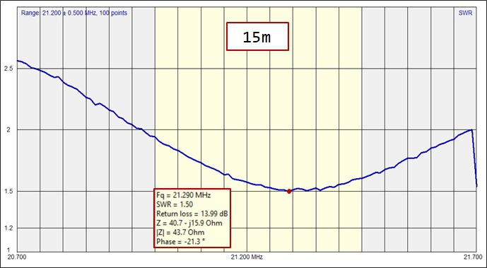
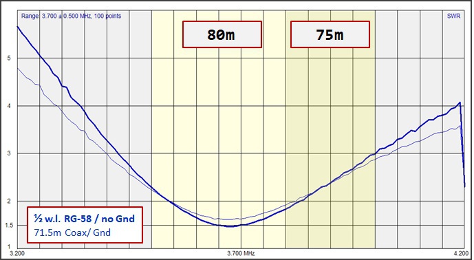
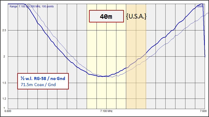
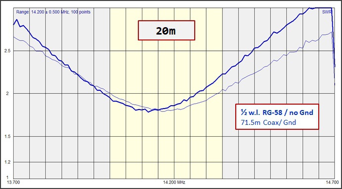
GALLERY OF SWR CURVES (1/2 e-w.l.) :


NEXT, after adding the RMU-2 and pruning the overall length for best compromise, still with 1/2 e-w.l. of coax on 80m:
GALLERY OF SWR CURVES:
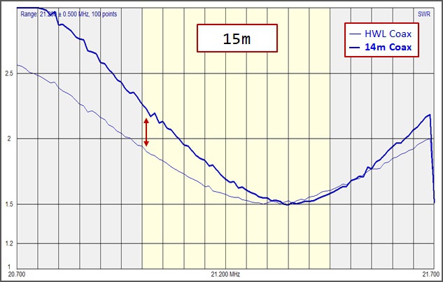
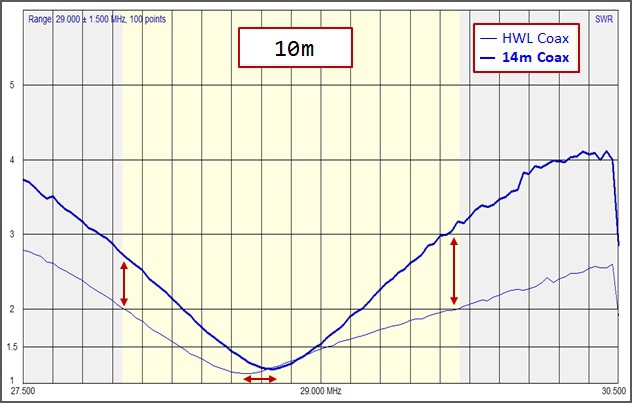
INTERIM MEASUREMENT: Measured at the first 14m of Coax running down the Pole.
Measuring at this position along the feedline highlights two points. See if you can spot them. I will disclose them below the SWR Curves.

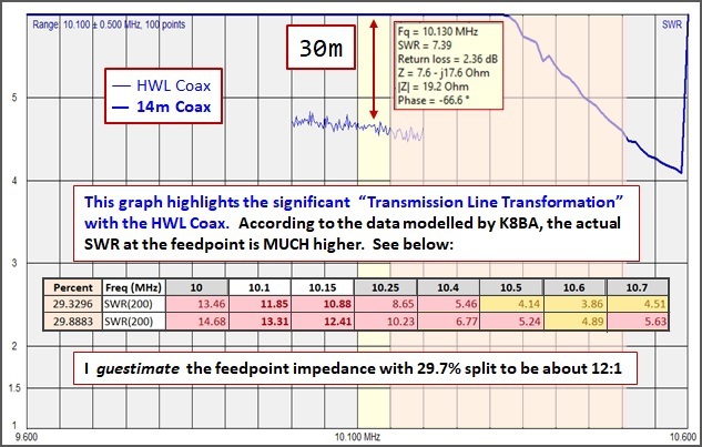


What you should have noticed is that most bands' curves were similar, but 12m and especially 30m had huge differences. Here is 30m again:

Note: the difference in shape of the SWR curve is due to the level of SWR with the 14m of coax attached is out-of-range of the ANTscope software's display range.
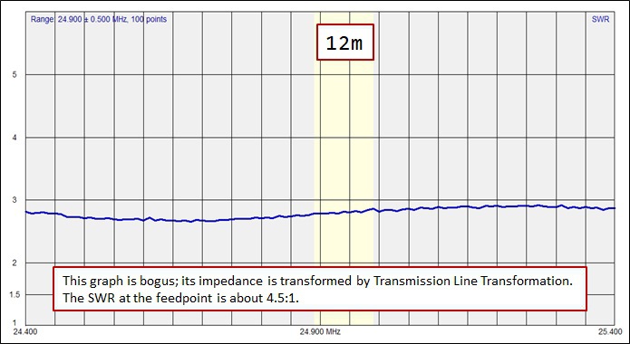
And here again is 12m:
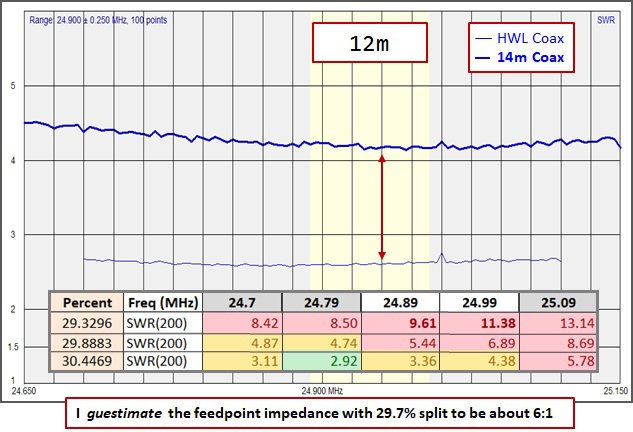
This graph shows the large difference in SWR between the two different lengths of coax. In addition, if you study the table of SWR by split, you will notice that the higher the split ratio, the better the SWR gets on 12m.
Increasing the split ratio to about 31% lowers the SWR to a favorable level. Unfortunately, looking back at the table on 30m, we see that increasing the split ration causes the SWR on 30m to go up. It's a compromise!
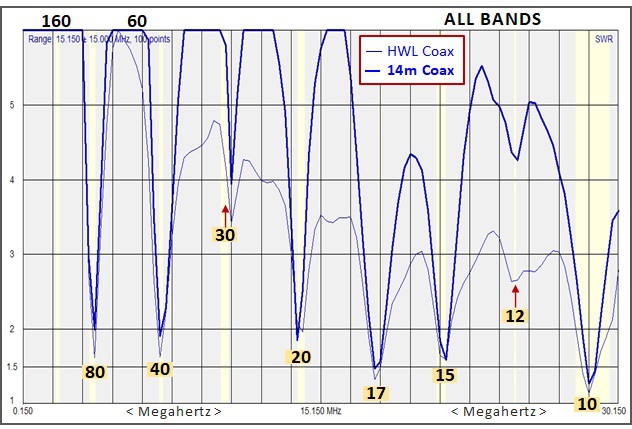
WHAT WE LEARNED from comparing the 14m curves to the HWL curves:
1) For most bands (i.e., all classic hf bands + 17m), the SWR at the feedpoint is relatively low. Changing the length of coax resulted in little change in the level of SWR
2) For bands with high SWR at the feedpoint, changes in length of coax result in large changes in the level of SWR.
FINAL NOTE: Although the SWR on both 30 and 12m is high, using the antenna together with a matchbox produces very good On-The-Air results. This is probably hard to believe by those of you who prefer reading text books, rather than building antennas and getting on the air with them! (But it's true.)
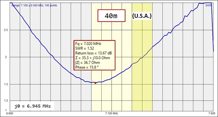
FINALLY: GALLERY OF SWR CURVES IN THE SHACK
In this group of curves, I compare the measurements in the shack (with a 1:1 Maxwell Choke attached to the antenna analyzer) to the measurements with 1/2 e-w.l. of RG-58 AU coax.

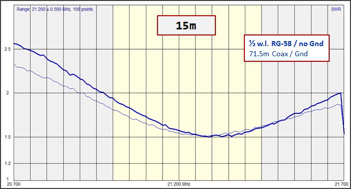

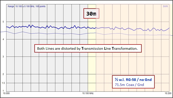
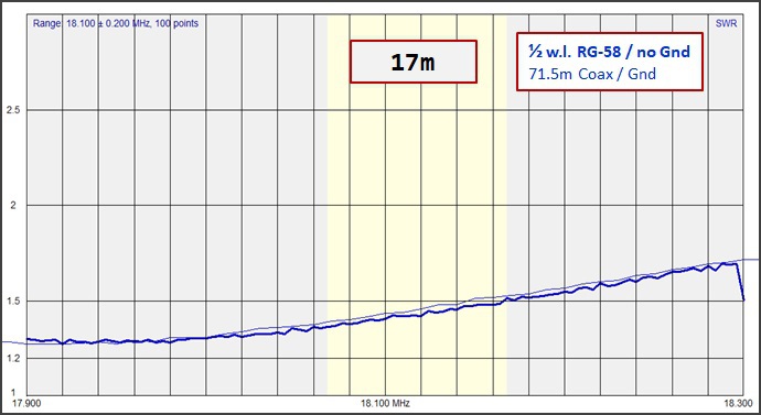
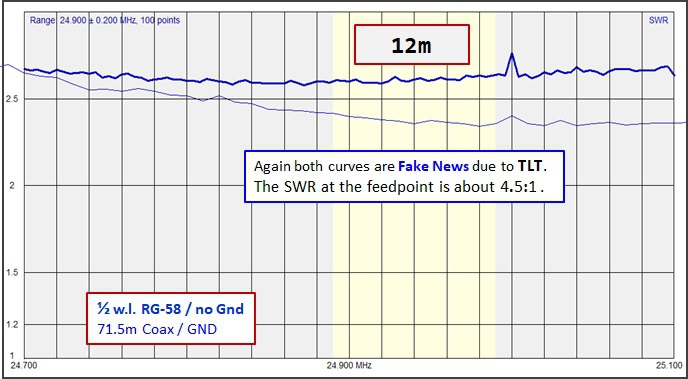
Again we find that ALL Classic HF Bands + 17m are very close to the measurements seen with 1/2 e-w.l. of coax attached. The SWR curves on 30m and 12m are skewed, due to Transmission Line Transformation.
CONCLUSION:
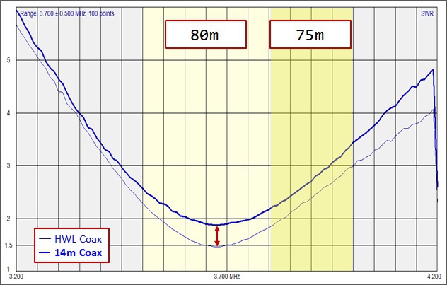
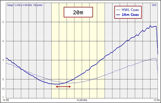
The fact that the SWR on the Classic HF Bands (and 17m) varies very little with changes in the length of coax indicates that the SWR at the feedpoint is fairly good on these bands.
The SWR (measured in the shack) on the other two WARC bands (30m & 12m) varies considerably with changes in the length of coax. This indicates that there is a high SWR at the feedpoint on these bands.
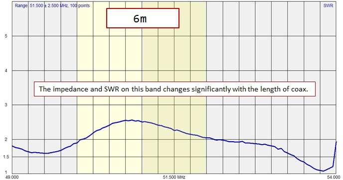
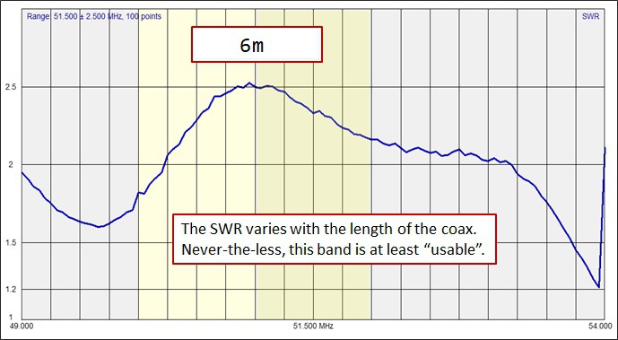
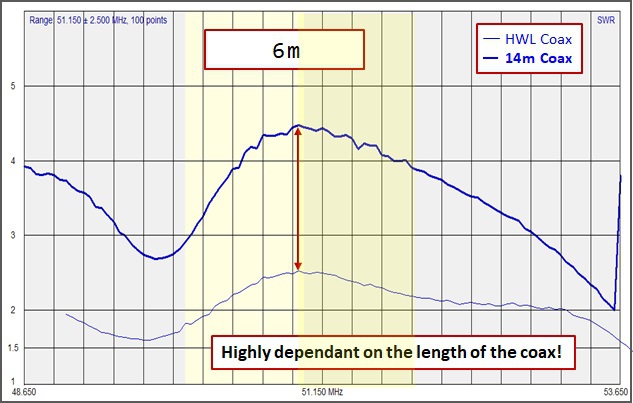
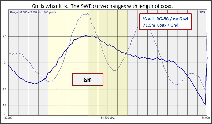
6m SWR is all over the map, depending on the length of coax attached to the antenna. This is normal for any long) wire antenna used on 6m. Operators with serious interest in 6m will use a separate, dedicated antenna for this band. Never-the-less, we can work 6m with this antenna.
The 807-HDL is usable on 9 bands, albeit with an antenna
matchbox on part of 80/75m and two of the WARC bands.