


20m SWR Abnormality
After having measured 807-xx antennas in the field at least 30 or 40 times, I know what to expect when I measure one.
On 20m, the SWR curve with 2 wavelengths of RG58 AU attached normally looks like this:
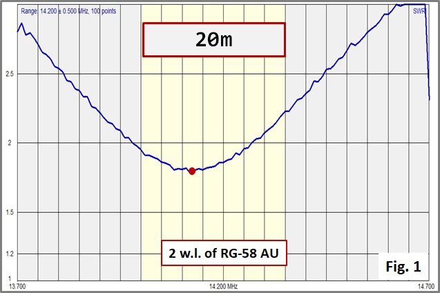
Notice that the SWR is under 2:1 for most of the band, rising to about 2.3:1 at the high end of the band. This is how it almost always looks.
Next, I scanned the SWR curve with the 14m of Airborne-5 Coax running down the pole from the antenna. This is position (2) 'Mast' in the drawing below. It too looked good, but only at first glance:
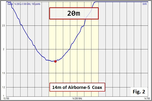
The SWR curve was 'almost' OK there. The frequency of minimum SWR had fallen slightly, and the shift caused the SWR at the high end of the band to be >3:1. This is not good.
Never-the-less, I continued and measured the antenna again at the next junction of coax (3) on the terrace:
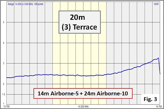
Clearly there was Something Rotten in Denmark!
So let's first take a closer look at the coax between the antenna and the house. It consists of 4 pieces of coax:
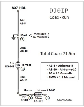
Description of Coax Run:
1) 14m of Airborne-5 running up the pole.
Note that the shield grounds at this point.
2) 24m of Airborne-10 to the terrace
This, together with the first 14m is 1/2 w.l. on 80m. I inserted a 1:1 Guanella Choke at this point.
3) 30m of Airborne-10 to the house
4) 2m of RG8U into the house to the rig
I inserted a 1:1 Maxwell Choke between the coax and the rig.
I first measured the SWR at position (2), then position (3), and finally I measured it in the shack (4) and (5). I saw no value in measuring at the bottom of the 30m AB-10.
I should have been suspicious of the measurements at (2), because a shift in the frequency of minimum SWR is one of the negative effects caused by Common Mode Current. Instead, I ignored it and hoped for the best.
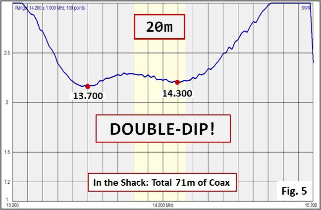
After measuring the SWR at position (3), the terrace, I knew something was dreadfully wrong; but what? The Double-Dip in the SWR curve did not appear with the 1 MHz scan (Fig. 2). I didn't detect it until I ran a 2 MHz and 3 MHz scan, but then it was apparent.
My "Standard" 1 MHz Scan:

A 2 MHz Scan:
I smell TROUBLE!
I began this section by stating that I have measured these antennas 30 or 40 times. This is fact, not exageration.
Although I have never seen this this Double-Dip before on this specific antenna, I have seen it before!
I was fairly sure this was being caused by
Common Mode Current on the feedline.
SUMMARY:
This specific antenna was measured with 1/2 (electrical) wavelength of RG-58 AU coax on 80m (which is 2 w.l. on 20m), with 15m of RG-142 CU coax, and with 14m of Airborne-5 coax.
All curves on all 3 pieces of coax looked nearly identical on the classic HF bands as well as 17m. The 30m and 12m curves changed considerably due to transmission line transformation - which was to be expected.
When the 14m of AB-5 was extended with 24m of AB-10, plus 1m of coax in the 1:1 Guanella Choke, for a total of 39m (physical) of coax, the problem appeared. "39m" (physical) is approximately 1/2 physical w.l. on 80m (or, 2 w.l. on 20m), which is a length that repeats the conditions at the feedpoint. In other words, this is a point to expect the highest level of Common Mode Current.
The Obvious: the problem is due to this specific length of coax.
But wait, I also had this problem in the shack, which is not a multiple of a half wavelength of coax on 80m.